
Micro CNC Machining
Micro CNC Machining — fine features and GD&T controls from Dongguan, CMM-verified. Tolerances: ±0.003 mm milling, ±0.002 mm turning — ISO 9001 / IATF 16949 verified.
Micro CNC machining is geometry at a scale where every control matters. This page covers the geometric controls a machined part carries and how form, location and material condition work.
What is micro CNC machining?
Micro CNC machining is CNC machining at small scale — fine features, thin walls, small tools — where every geometric control matters more because the tolerances do not scale down with the part. The drawing's geometric controls — form, location, profile — are what the machine must hold and the CMM must check.
The full GD&T symbol set has 14 symbols in five groups. Not all of them appear on every drawing, but a machining shop that reads GD&T should recognize all 14 and know which ones its machines actually hold.
| Group | Symbols | What they control |
|---|---|---|
| Form | Straightness, Flatness, Circularity, Cylindricity | The shape of a feature by itself, no datum |
| Orientation | Parallelism, Perpendicularity, Angularity | The angle of a feature to a datum |
| Location | Position, Concentricity, Symmetry | Where a feature sits relative to a datum |
| Profile | Profile of a line, Profile of a surface | The contour of a surface, with or without datum |
| Runout | Circular runout, Total runout | Wobble of a rotating surface around a datum axis |
On machined metal parts, five symbols do most of the work: position for hole patterns and dowel pins, cylindricity for bearing journals, flatness for sealing faces, perpendicularity for mounting faces, and runout for rotating features. Profile of a surface shows up on contoured parts. Form controls like straightness and circularity usually appear on shafts and spindles.
Each symbol answers a different question. Flatness asks "how flat is this face?" Position asks "where is this hole relative to the datums?" Cylindricity asks "is this journal a true cylinder, or an egg?" A part can carry several answers at once, and the CMM program measures them all from the same datum structure.
The practical takeaway: when you see a symbol on a drawing, it tells the shop what to hold and the CMM what to check. A drawing that names the symbol but no datum for a location control is incomplete, and a shop that quotes it without asking has not read it.
Which geometric controls can a machined part carry?
The control tells the shop what to hold and the CMM what to check. Each one governs a different kind of error, and a single part can carry several at once.
| Control | What it governs | Typical feature |
|---|---|---|
| Position | Location of a feature | Hole patterns, dowel pins |
| Cylindricity | Roundness along a shaft | Bearing journals |
| Concentricity | Coaxial alignment | Stepped shafts |
| Flatness | Planar deviation | Sealing faces |
| Perpendicularity | Squareness to a datum | Mounting faces |
| Circular runout | Roundness plus location at one section | Rotating diameters |
| Total runout | Combined surface control along a length | Spindle journals |
A part that carries a position tolerance on a hole pattern and a perpendicularity tolerance on its mounting face is asking for two different measurements. The CMM handles both in one program, but only if the datum structure is the same for both. That is why the datum is checked before the controls are machined: one datum, one coordinate system, and every control hangs off it.
The controls also stack. A flatness tolerance on a face and a perpendicularity tolerance on the same face are two different requirements — one asks about the face itself, the other about its angle to a datum. The machinist has to satisfy both, and the CMM has to report both. A shop that reads only the tighter number is only doing half the job.
How do form controls differ from location controls?
Form controls describe a feature on its own. Location controls describe a feature relative to something else. The difference is the datum: form controls usually need none, and location controls always need one.
Flatness, straightness, circularity, and cylindricity are form controls. They ask how flat, how straight, or how round a feature is, without caring where the feature sits. A flatness tolerance of 0.010 mm on a sealing face means the face must lie between two parallel planes 0.010 mm apart — no datum required.
Position, concentricity, and symmetry are location controls. They ask where the feature is relative to a datum. A position tolerance of 0.050 mm at MMC (maximum material condition) on a hole pattern means each hole axis must fall inside a cylindrical zone whose position is fixed by the datums.
The practical consequence for machining is order of operations. Form comes first: a face is flattened before it becomes a datum for the next setup. A shop that machines a location feature before establishing the datum it references is building on sand. The DFM review checks that the sequence respects the datum, because a control is only as good as the datum under it.
Orientation controls sit between form and location. Parallelism asks that a face stay parallel to a datum plane; perpendicularity asks that it stay square; angularity asks that it stay at a stated angle. These matter because a face that is flat but not perpendicular to its datum will bolt up skewed, and the error only shows at assembly. On a machined part, perpendicularity on a mounting face is the control that keeps a housing from leaning when it is bolted down.
How do material condition modifiers (MMC, LMC, RFS) change the tolerance?
A material condition modifier in the feature control frame tells the shop how the tolerance behaves as the feature size changes. The three choices are MMC (maximum material condition), LMC (least material condition), and RFS (regardless of feature size).
MMC is the workhorse for hole patterns. It means the tolerance applies when the feature has the most material — for a hole, when it is drilled at its smallest allowed size. As the hole is drilled larger, it gains a bonus tolerance equal to the departure from MMC. A hole that can be larger without breaking the fit becomes easier to position, which is exactly the right trade.
The practical payoff is gauging. A position tolerance at MMC can be checked with a functional gauge — a fixed pin that either enters the hole or does not. That is faster than a CMM and still valid, which is why MMC shows up on production hole patterns. RFS, by contrast, has no bonus and must be measured, usually on a CMM.
For you, the modifier is a cost signal. MMC loosens the shop's job without loosening the function, so it is cheaper to machine and faster to inspect. A drawing that defaults every control to RFS is paying for measurement precision the design may not need.
How does runout work, and when does it replace concentricity?
Runout measures how much a rotating surface wobbles as the part turns around a datum axis. Circular runout checks a single cross-section; total runout checks the whole surface along its length, combining roundness, straightness, and coaxiality into one control.
Runout is easier to measure than concentricity, and that is why it shows up more often on shop drawings. Concentricity asks whether the median points of two diameters share an axis — a mathematically clean but hard-to-measure idea. Runout asks a simpler question: when I spin the part, does the surface stay within a zone? The answer comes off a dial indicator or a CMM scan, not from a derived axis.
For a rotating part — a spindle, a pulley, a gear blank — runout is the control that predicts how it will behave in use. A part that meets runout is balanced and true; a part that only meets a size tolerance can still shake itself apart at speed. When a drawing calls concentricity on a shaft, a good shop will confirm whether runout is what the design actually needs, because runout is the control that gets measured reliably on the floor.
There is a second reason runout wins in practice: it bundles several controls into one. Total runout on a journal covers roundness, straightness, and coaxiality in a single indicator sweep, which is cheaper to inspect than three separate CMM programs. For a rotating feature, runout is often the one control that replaces three.
How is a fit specified and verified?
A fit is how two mating features relate — clearance, transition, or interference — set by their tolerance zones. The CMM checks each feature against its datum and verifies the resulting fit before the parts ship. A bearing seat and its mating journal are not just two dimensions; they are one fit, and the tolerance zones decide whether it clears, presses, or seizes.
The three classes are named for what happens at assembly. A clearance fit always leaves a gap — the shaft is smaller than the hole. A transition fit may clear or press, depending on where the actual sizes land. An interference fit always presses — the shaft is larger than the hole, and assembly needs force or heat.
In the ISO system, fits are written as a letter-and-number pair, such as H7/g6. The capital letter is the hole, the lowercase letter the shaft, and the number is the tolerance grade. H7/g6 is a common running fit; H7/p6 is a light press. The point for you is that the fit is a system, not a single number — you choose the hole and shaft together, and the CMM confirms the resulting clearance or interference is what the pair actually produces.
| Fit class | ISO examples | What happens at assembly |
|---|---|---|
| Clearance | H7/g6, H8/f7 | Shaft always smaller than hole; free to rotate or slide |
| Transition | H7/k6, H7/n6 | May clear or press; needs a light tap or aligns dead center |
| Interference | H7/p6, H7/s6 | Shaft always larger; pressed or heated into place |
The second-order point: a fit checked as two separate sizes is still a guess. The CMM reports the relationship, not just each feature's dimension, so a clearance that looks fine on paper is confirmed in the measured result before it ships.
The hole-basis and shaft-basis systems are the two ways to build a fit. In the hole-basis system, the hole keeps a fixed position letter — H — and the shaft letter is chosen to set the fit, which is the more common approach because holes are harder to rework than shafts. In the shaft-basis system, the shaft keeps a fixed letter and the hole is varied. You do not need to memorize the letters; it is enough to know that the pair is a system, and the CMM confirms what the pair actually produces, not what the letters promise.
What micron-scale tolerance can the shop actually hold?
The number is tied to the process, not a claim. CNC milling and turning hold ±0.003 mm (milling) / ±0.002 mm (turning), and precision grinding holds ±0.002 mm for roundness-critical surfaces. On a representative length characteristic (76.1–76.5 mm), our SPC shows Cpk 1.851 (one characteristic on one part, not a blanket capability claim) against an initial-study target of Ppk ≥ 1.67.
| Process | Held tolerance | Typical use |
|---|---|---|
| CNC milling | ±0.003 mm | Housings, locating features |
| CNC turning | ±0.002 mm | Journals, pins, bushings |
| Precision grinding | ±0.002 mm | Bearing seats, roundness-critical surfaces |
A tolerance is only meaningful with the process behind it. A shop that states ±0.003 mm (milling) / ±0.002 mm (turning) but machines on worn spindles will not hold it in production, no matter what the brochure says. The difference is measured: Cpk 1.851 (one characteristic on one part, not a blanket capability claim) on a length characteristic means the process is centered and its spread sits well inside the band. Ask for the chart, not the slogan.
There is also a hard physical limit under the number. The more than 100 machines on the floor include Mazak, Brother, Tsugami, and Sodick — a known-brand line means spares, service, and predictable thermal behavior across shifts. A stable machine is what turns a stated tolerance into a repeatable one.
Temperature is the quiet variable behind every tight number. A micron-level band only means something at a stated measurement temperature, because metal grows and shrinks with heat. A part machined warm and measured cold is a different size than the same part machined cold and measured warm. The shop's inspection bench measures at a controlled reference temperature, and the CMM compensates for thermal drift, so a ±0.003 mm (milling) / ±0.002 mm (turning) band means the same thing at the shop as it does at your lab.
How does ISO 2768 cover the dimensions a drawing does not tolerance?
Not every dimension on a drawing carries an explicit tolerance. ISO 2768 is the general-tolerance standard that catches the rest, so the drawing stays clean and every dimension still has a limit. It sets two things: general tolerances for linear and angular dimensions, and general geometric tolerances for form and position.
The standard uses four tolerance classes. Class f is fine, m is medium, c is coarse, and v is very coarse. A drawing names its class in the title block — for example, "ISO 2768-m" — and every untoleranced dimension inherits that class's limit based on its nominal size. A 30 mm linear dimension under ISO 2768-m carries a tolerance in the range of roughly ±0.2 mm, while a 300 mm dimension carries a wider one.
The same logic covers geometry. ISO 2768 also sets general limits for straightness, flatness, and perpendicularity on features that have no explicit control, keyed to the nominal length. That is the safety net that keeps a drawing with no GD&T from leaving every form error unstated.
The practical point for a machined part is that ISO 2768 is the floor, not the ceiling. It covers dimensions that do not need a specific band. Anything that matters — a bearing seat, a locating face, a hole pattern — should carry its own GD&T control, because a general tolerance is a catch-all, not a design decision. The DFM review flags dimensions that are relying on ISO 2768 but should not be.
The general linear tolerance steps by nominal size, so the band widens as the dimension grows. A short feature under a fine class carries a tight general limit; a long feature under the same class carries a wider one. This is the standard's way of staying realistic, because a long dimension is harder to hold than a short one, and the class you name in the title block is the one limit that covers every dimension you did not bother to tolerance.
How do material choice and geometric tolerance interact?
The material sets how tight a geometric control can practically go, and how stable the result stays after the part cools and settles. A tolerance that holds in aluminum may not hold in the same geometry cut from stainless, and a part that measures perfect on the CMM can move overnight if the material is still releasing stress.
Aluminum 6061-T6 and 7075-T6 cut predictably and shed heat well, so position and flatness hold cleanly. Stainless 304 and 316 work-harden at the tool edge, run slower, and can warp as internal stress redistributes. Alloy steel 4140 is stiff and stable, which is why it carries bearing seats and spindles that must hold roundness after heat treatment.
| Material | Machining behavior | Effect on geometric tolerance |
|---|---|---|
| Aluminum 6061-T6 | Fast, free-cutting, sheds heat | Holds position and flatness cleanly |
| Aluminum 7075-T6 | Strong, slightly harder to cut | Holds tight bands; watch for stress relief |
| Stainless 304 / 316 | Work-hardens, slow feeds | Needs sharp tools; warp risk on thin walls |
| Alloy steel 4140 | Stiff, stable, heat-treatable | Holds roundness after heat treatment |
| Brass / copper | Free-cutting, clean chips | Good for threads and turned fits |
The second-order point is thermal. A part measured at 22 °C has a different size at 30 °C, and the coefficient of thermal expansion differs by material. A tight fit between an aluminum housing and a steel shaft changes clearance with temperature. The rule: let the material drive the process and the inspection condition, and do not force a tight band onto a grade that cannot hold it.
How does surface roughness (Ra) relate to tolerance and fit?
Surface roughness is a different measurement from size, but they travel together. Ra is the arithmetic average of the surface profile, expressed in micrometres. A machined part might hold a size to ±0.003 mm (milling) / ±0.002 mm (turning) and still have an Ra that is wrong for the function — too rough for a sealing face, too smooth for a press fit that needs grip.
Common Ra targets for machined metal sit in a practical ladder. As-milled and as-turned surfaces often land around Ra 1.6 µm to 3.2 µm. A ground surface drops to Ra 0.4 µm to 0.8 µm. A polished or lapped face can go below Ra 0.2 µm. The ladder maps to cost: a smoother finish needs slower feeds, finer wheels, and more inspection, so the Ra you call out is a price decision, not just a quality decision.
| Surface finish | Typical Ra | Where it is used |
|---|---|---|
| Milled / turned | 1.6 – 3.2 µm | General housings, brackets |
| Ground | 0.4 – 0.8 µm | Bearing seats, journals |
| Polished / lapped | 0.05 – 0.2 µm | Sealing faces, optical seats |
The fit connection is direct. A clearance fit between a shaft and a bore depends on the peaks of the two surfaces, not just the nominal sizes. A rough surface with high peaks can turn a designed clearance into an interference. That is why the surface finish is specified alongside the fit, and why the inspection bench measures roughness with a profilometer, not a guess.
What DFM rules keep a GD&T drawing machinable?
A toleranced drawing is only useful if the part can actually be cut. Design-for-manufacturing rules exist to keep the GD&T achievable, and the DFM review reads them before the first cut.
Wall thickness is the first check. A wall that is too thin deflects under the tool, so a tight flatness or position tolerance becomes impossible to hold no matter how good the machine is. The rule of thumb is to keep walls thick enough to resist the cutting force, and to call tight bands only on features with enough stock to support them.
Hole depth is the second. A deep hole with a tight position tolerance needs a long, flexible drill that wanders. The rule is that a hole deeper than about three to four diameters starts to sacrifice position, and a tight position on a deep hole should be flagged before quoting.
Internal corners are the third. A mill leaves a radius equal to the tool radius, so a sharp internal corner in the model is not machinable as drawn. A drawing that specifies a square corner is asking for an impossible geometry, and the DFM review will convert it to the minimum tool radius or add a relief. These three checks — wall, hole, corner — are where most GD&T drawings first run into reality, and catching them on paper is the cheap way to keep the tolerance honest.
Two more rules follow the same logic. Thin features and long unsupported spans deflect under cutting force, so a tight straightness or flatness control on a long, thin part needs a setup that supports it, or a relaxed band. And a part that needs a tight band on a bore should have the bore finished after any heat treatment, because heat treatment moves metal, and a bore that was tight before the furnace will not be tight after it. The DFM review sequences the operations so the tight feature is finished last, on the process that can actually hold it.
How are geometric tolerances inspected?
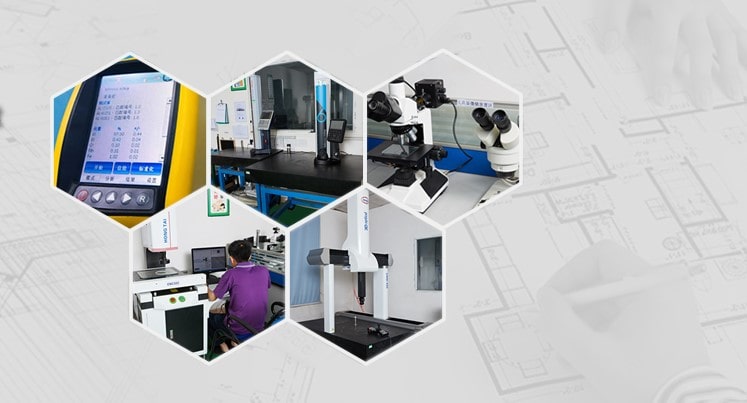
Geometric controls are verified on Hexagon GLOBAL S CMMs, which build the datum reference frame and measure position, cylindricity, and the rest against it. A KEYENCE VK-X3000 laser microscope and a SURFCOM 1800D support surface finish and profile, so the measurement matches the control on the drawing.
A CMM does not just check a dimension; it probes points and fits the geometry — a plane for flatness, a cylinder for cylindricity, an axis for position. The measured feature is compared to its tolerance zone in the software, and the report shows the deviation with the datum structure it was measured against. That report is the difference between a part that fits and a part that was assumed to fit.
For you, the inspection method is as important as the tolerance itself. A caliper measures size at a point. A CMM measures the geometry the GD&T actually calls out. When the drawing asks for position or cylindricity, the answer has to come from the instrument that can measure it, not from the one that happens to be on the bench.
The same CMM program written for your first article is the program that inspects the production run, so there is no re-baselining between prototype and volume. The validation carries forward, which is why the first article report matters: it fixes the measurement method for every part that follows.
Measurement repeatability is what separates a useful report from a one-off reading. A CMM that returns the same number on the same part, probed twice, is trustworthy; a measurement that drifts between readings is a guess dressed up as data. The bench here runs the same class of Hexagon CMM your lab would use, and the report states the deviation against the datum, so you can reproduce the number instead of taking it on faith.
Why does a GD&T drawing cost less in the long run?
A GD&T drawing costs less because it leaves nothing to interpretation. Every feature is defined against a datum, so the shop machines what you meant, the CMM measures what you meant, and a disagreement at the dock cannot happen. The cheapest way to make a precise part right is to specify it precisely.
The savings show up where disputes used to — the dock, the rework queue, and the email thread arguing over what the drawing meant. A part that is fully specified never triggers a round of "what did you actually need here." A part that is under-specified always does, and that round-trip costs time, freight, and trust.
There is a second, quieter saving. A toleranced drawing lets the shop choose the cheapest process that still meets the band. Over-tolerancing forces a grinder where a mill would do, and the grinder costs more. When the drawing is clear, the shop can pick the process that earns the tolerance instead of the one that overshoots it. Clarity is a cost lever, and GD&T is the tool that pulls it.
How do you decide which tolerance band is worth paying for?

Not every feature earns a tight band. A housing that locates a bearing seat may hold ±0.003 mm (milling) / ±0.002 mm (turning), while the seat itself drops to ±0.002 mm on the grinder. The rule: specify the tightest band only where the fit or function actually needs it, and let the rest of the part run looser. Over-tolerating every feature raises cost and inspection time without raising part quality.
| Feature | Process | Held tolerance |
|---|---|---|
| Bearing seat, roundness-critical surface | Precision grinding | ±0.002 mm |
| Housing, locating feature, journal | CNC milling / turning | ±0.003 mm (milling) / ±0.002 mm (turning) |
| Non-critical clearance, cosmetic face | Standard machining | ISO 2768 general tolerance |
Each band is verified against its datum, so you pay for measurement only where a control actually lives on the drawing. The disciplined question is not "how tight can you go" but "which three dimensions on this part actually matter." Tolerate those tightly, and leave the rest at the general level. The part comes out cheaper, and the inspection report focuses on the features that decide whether it works.
The tolerance ladder also tracks the price ladder. A ±0.003 mm milled feature costs one thing; a ±0.002 mm ground seat costs more because it adds a grinding setup and a finer inspection step. When the drawing splits the two bands correctly, the extra cost lands only where the function demands it, and the rest of the part rides the cheaper process.
The same logic applies to the number of bands you use. A part with three tolerance levels — general, milled, ground — is cheaper and clearer than a part where every dimension carries its own bespoke number. Fewer bands means fewer setups, fewer inspection programs, and fewer places for the drawing to contradict itself.
Where does micro CNC machining with GD&T show up across industries?
The same GD&T discipline serves several industries, each with a different feature that earns the tight band. The common thread is that a small, precise feature has to mate with something else, and the fit decides whether the assembly works.
In medical devices and surgical instruments, position and concentricity on small stainless and titanium parts decide whether a mechanism articulates cleanly. In robotics and automation, hole patterns and mounting faces carry position and perpendicularity controls so actuators and frames bolt together square. In semiconductor and optical equipment, flatness and profile controls keep sealing faces and lens seats within microns.
In e-bike and electric drivetrain work, the rotating parts — spindles, gear blanks, and motor housings — carry runout and cylindricity so the assembly spins true instead of shaking. In general precision equipment, bearing seats and journals are ground to ±0.002 mm because a bearing only lives as long as its seat stays round.
The takeaway is the same in every case: the industry names the feature, and GD&T names the number. A shop that reads the symbols can serve all of them, because the discipline does not change — only the part does. The MOQ of 1 piece means a single prototype in any of these industries can be validated on the same drawing and process that will run the production volume.
Regulation only sharpens the same requirement. A medical or automotive buyer still needs the same datum, the same tolerance, and the same inspection report — the difference is that the evidence has to be documented and traceable, not just produced. A shop that already runs GD&T to a measured Cpk has that documentation as a matter of routine, so the jump to a regulated program is a paperwork step, not a capability step. The geometry does not get harder when a part is regulated; the proof does.
What goes wrong when a drawing skips GD&T?
When a drawing has sizes but no geometric controls, the shop is left to guess what the designer meant, and the guess is made at the machine, not at the desk where it is cheap. The failure shows up in predictable ways.
A hole pattern drawn with only diameters will be machined to the right size and possibly the wrong position, because position was never specified. A shaft drawn with only diameters will be round within the lathe's habit, not within a stated cylindricity zone. A mating pair drawn without a fit will arrive as two parts that each measure fine and still do not go together, because the relationship was never on the drawing.
The red-flag version is a shop that quotes such a drawing without asking a single question. A shop that reads GD&T will flag the missing datums before quoting, because it knows the parts cannot be verified without them. A shop that quotes blind is pricing a part it has not understood, and the misunderstanding becomes your scrap. The fix is not more inspection downstream — it is a complete drawing upstream.
There is also a quieter failure: a drawing that skips GD&T hides the cost of over-tightening. Without geometric controls, a designer often tightens every size to be safe, and the shop machines every feature to that tight band whether it needs it or not. The part costs more than it should, and the designer never learns which features actually mattered. GD&T fixes that by naming the few features that earn the tight band and letting the rest relax.
The reverse failure is worth naming too: a drawing with GD&T but no discipline behind it. A control that names a datum the shop cannot actually locate, or a tolerance the machine cannot hold, is a wish wearing a symbol. That is why the DFM review reads the GD&T before quoting, not to reject the drawing, but to confirm that every control on it can be machined and measured. A control the CMM cannot verify is a control the shop cannot hold.
What should you ask a micro machining supplier before you send the drawing?
- Where does the datum structure come from, and does the DFM review read the GD&T or only the dimensions?
- Which instruments verify position and cylindricity — a CMM, or a caliper?
- What Cpk do you hold on a representative characteristic, and how does it compare to a Ppk ≥ 1.67 initial-study target for key characteristics?
- How is a fit confirmed before shipping — clearance, transition, or interference, measured against the datum?
- Do you recognize all 14 GD&T symbols, and can you machine the ones on my drawing?
- What are the certificate numbers, and can I confirm them with the registrar?
- How does the process sequence preserve the datum across turning, milling, and grinding?
- Which material condition modifiers do you handle, and do you gauge MMC hole patterns or measure them?
These are the questions that separate a shop that reads the drawing from a shop that reads the part number. A supplier that can answer all of them in writing, before you spend anything, is one whose tolerance you can rely on.
Guides
- Micro CNC machining cost in 2026 — your cost model where the GD&T sets the price.
What this shop actually runs
A buyer asking for capability evidence should get a specific answer. The facility behind this guide operates 100+ CNC machines across a 6,800 m2 plant in Dongguan, China, with 100+ staff. The machine list by category:
- 5-axis machining centres (10+) - Mazak VARIAXIS I-600 (510/910/510 mm travel, 12,000 rpm, 22 kW, 71.6 N·m, 30-tool BT40) and Mazak INTEGREX I-250H S (B-axis 0.0001°, 24 kW, 124 N·m, 38-tool HSK-A63). Chosen for compound-angle parts, single-setup multi-face prismatic work, and aerospace fittings where datum transfer loss is unacceptable.
- 3-axis / 4-axis machining centres (50+) - Brother SPEEDIO S500Z2N / S700Z2N (10,000 rpm, 14/21-tool ATC, 0.7 s tool-to-tool, Z-axis 2.2 G) and Mazak VCE-430A L / VCE-570C L (10,000 rpm, 118 N·m, 24-tool ATC). Chosen for prismatic parts, plates, brackets, housings.
- 100+ production machines — Mazak / Brother / Tsugami / Star / Citizen class, across a 6,800 m² facility (3-axis 50+, 4-axis 20+, 5-axis 20+, 25+ lathes, 7+ grinders, 20+ inspection instruments).
- Tolerance: ±0.002 mm, verified on Hexagon CMMs. Capability is reported per characteristic: Ppk ≥ 1.67 in the initial study and Cpk ≥ 1.33 in production on key and special characteristics (≥ 1.33 on general characteristics). Every report names the feature, its tolerance band, the sample size, the sigma method, and the study window.
- Three certificates — ISO 9001:2015, IATF 16949:2016 (design excluded) and ISO 14001:2015, all held by Dongguan Zhuohang Ltd, the entity that invoices you.
- Order terms: a one-piece minimum and lead times around 3, 7 or 30 days, set by part complexity.
- Machine highlights - VARIAXIS I-600: one-setup multi-face 5-axis + MAZA-CHECK auto-calibration; INTEGREX I-250H S: DONE-IN-ONE mill-turn, B-axis 0.0001° + Ai thermal shield; SPEEDIO S500Z2N / S700Z2N: Z-axis 2.2 G + 0.7 s ATC; Swiss-type: guide-bush switchable + 0.1 µm resolution.
Tolerance bands held: ±0.003 mm on CNC milling, ±0.002 mm on CNC turning, ±0.002 mm on precision grinding and wire EDM. Capability indices: Ppk >= 1.67 initial on key characteristics; Cpk >= 1.33 ongoing in production.
Certifications: ISO 9001:2015 (116024/A/0001/UK/En), IATF 16949:2016 (131941/A/0001/SM/En, design clause 8.3 excluded - disclosed openly), ISO 14001:2015 (116024/B/0001/UK/En). Certificates are issued to Dongguan Zhuohang Ltd (USCC 91441900MA4UWT6X39, established 2005).
Service area: Austria, Belgium, the Czech Republic, Denmark, France, Germany, Greece, Hungary, Ireland, Italy, the Netherlands, Spain, Sweden and the United Kingdom in Europe; Brazil, Canada, Mexico and the United States in the Americas; China, Israel, Japan, Singapore and Sri Lanka in Asia; Australia and New Zealand in Oceania; and South Africa in Africa. Based in China, serving customers worldwide.
Contact: Felipe Iglesias, [email protected], +86 13126536955.
Get your GD&T read by an engineer
Send your drawing to [email protected] or call +86 13126536955 for a DFM review and quote.
Frequently Asked Questions
What is GD&T and why does it matter for machined parts?
GD&T (geometric dimensioning and tolerancing) defines how much a feature may deviate in form, orientation, and location, referenced to a datum. It turns a wish into a measurable requirement, which is the only kind a machine and a CMM can verify.
What are the 14 GD&T symbols?
In short, The 14 symbols fall into five groups: form (straightness, flatness, circularity, cylindricity), orientation (parallelism, perpendicularity, angularity), location (position, concentricity, symmetry), profile (profile of a line, profile of a surface), and runout (circular runout, total runout). Machined parts most often carry position, cylindricity, flatness, perpendicularity, and runout.
What tolerances can you hold?
±0.003 mm on CNC milling, ±0.002 mm on CNC turning, and ±0.002 mm for precision grinding. Critical dimensions are verified on Hexagon CMMs, with Ppk ≥ 1.67 at the initial study on key characteristics and ≥ 1.33 on general characteristics.
How exactly is a fit specified and verified?
Set the tolerance zones on both mating features, clearance, transition or interference, and reference them to a common datum. We probe each feature on the CMM and check the resulting fit before the parts leave the floor.
What is the minimum order quantity?
One piece. There is no forced production minimum, so you can machine a prototype, validate it, and scale into production on the same drawing and process.
How exactly are geometric tolerances inspected?
Hexagon GLOBAL S CMMs verify position, cylindricity, and other geometric controls against the datum structure, supported by a laser microscope and surface finish equipment.
How does ISO 2768 handle dimensions without a tolerance?
In short, ISO 2768 is the general-tolerance standard for untoleranced linear and angular dimensions and for general geometric tolerances, in classes f (fine), m (medium), c (coarse), and v (very coarse). A drawing that does not state a per-feature tolerance falls back to the class named in the title block.
What does MMC mean in a GD&T frame?
In short, MMC (maximum material condition) means the tolerance applies when the feature has the most material, so a hole gets a bonus tolerance as it is drilled larger. MMC also lets the shop use a functional gauge for position, which speeds inspection on hole patterns.
Which materials does the shop machine to GD&T?
Aluminum (6061, 7075), stainless steel (303, 304, 316), alloy steel (4140), brass, copper, titanium, and magnesium, plus engineering plastics. Incoming bar is XRF-checked against the mill certificate before machining.
How do I get a quote?
Email your STEP, IGES, or toleranced 2D drawing to [email protected]. The reply includes a DFM review that reads the GD&T and an itemized quote.
Do you use MIL-STD-105E or ANSI/ASQ Z1.4 sampling inspection?
In short, MIL-STD-105E is the U.S. military sampling inspection standard published in 1989; it specifies acceptable quality limit (AQL) sampling plans for lot-by-lot inspection.
Standards referenced on this page
- IATF 16949:2016 — Automotive quality management system standard
- ASTM E8/E8M-21 — Standard Test Methods for Tension Testing of Metallic Materials
- ISO 9001 — Quality management systems — Requirements